Blog
Exit Plan: What Happens When an OpenSFF Compute Node is Removed
Introduction
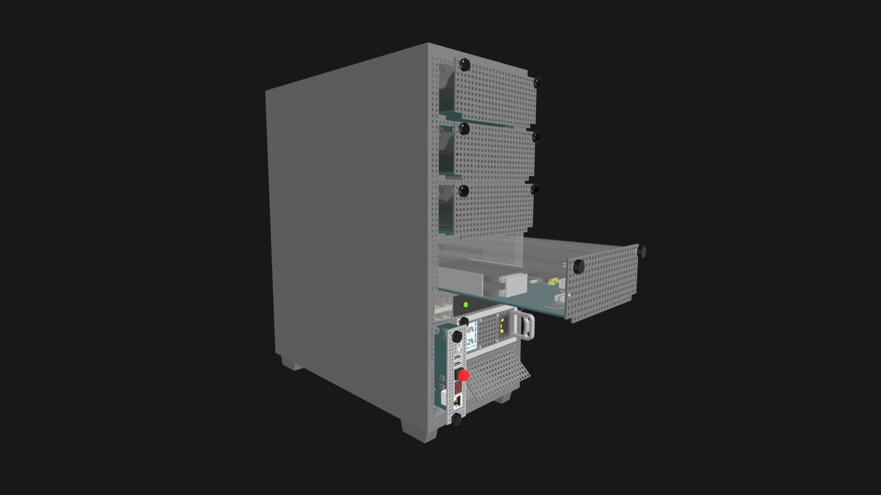
OpenSFF is a nonprofit organization creating an open hardware standard for small form factor systems. Our eponymous standard mainly comprises three hardware specifications. The Compute Node Specification defines a self-contained processing module. The Enclosure Specification defines a housing that provides power, cooling, and networking to one or more nodes. Finally, the Management Module Specification defines an optional node management component that provides KVM access and power control. These components can be combined to create a wide range of systems, from servers to edge devices, regardless of their vendors.
While our architecture is loosely based on blade servers, serviceability is one of our guiding principles. This is especially evident in how our modules are installed and removed from Enclosures. With traditional blade servers, pulling a blade out of its chassis isn’t a trivial operation. In this article, we’ll walk you through what happens when a Compute Node is properly pulled out of an Enclosure to explain why the process would be no harder than removing a stick of RAM.
Step 1: Unscrew the thumbscrews
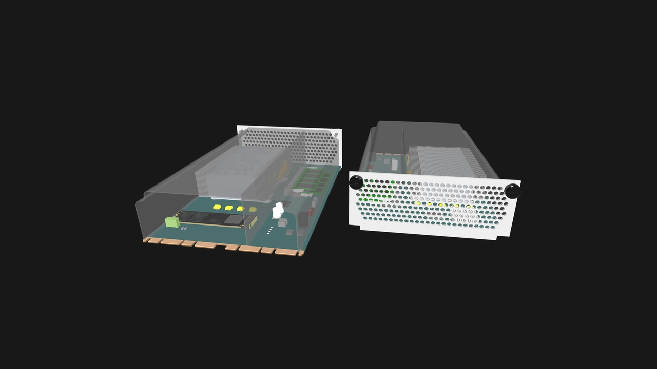
Every Compute Node (and Management Module) is fastened to an Enclosure by two captive M4 thumbscrews located at the upper corners of the module. As we mentioned in our deep dive on the thumbscrews, they’re purely retention mechanisms. A node’s card edge connector must fully mate with the receptacle on the Enclosure’s backplane without tightening the screws. As such, loosening the thumbscrews shouldn’t disengage the connection either.
Besides enhancing serviceability, our decision to use captive M4 thumbscrews is also driven by another OpenSFF core pillar: interoperability. M4 thumbscrews are standardized and widely available. This helps make any Compute Node compatible with any Enclosure instead of being restricted to one vendor’s latch design.
M4 thumbscrews are also cheaper to source and replace than a custom assembly. The savings cascade from vendors to users and compounds through every node slot in a deployment.
Step 2: Pull the node out
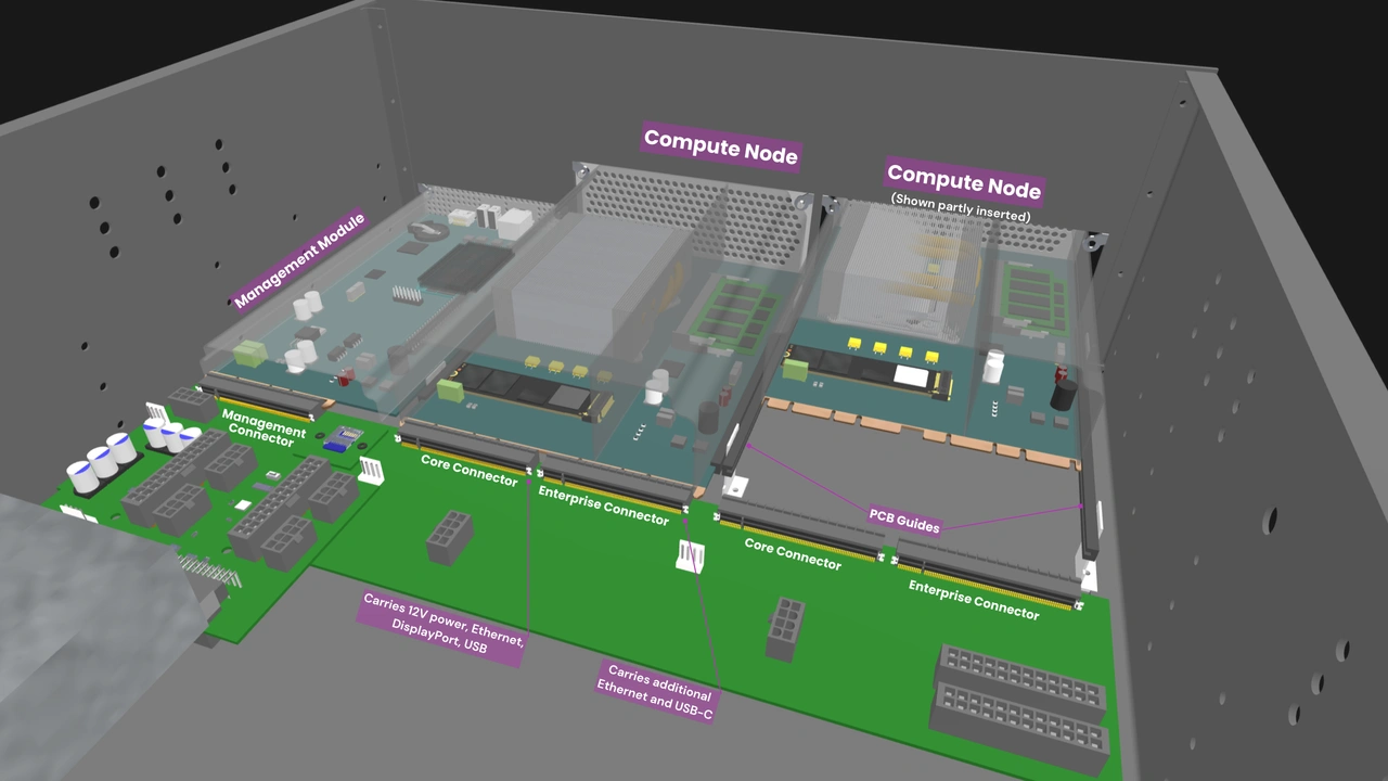
With both thumbscrews fully unscrewed, we can lightly tug at the Compute Node to disengage its card edge connector from the receptacle mounted on the Enclosure’s backplane. Nodes can have one or two SFF-TA-1002 4C+ connectors. SFF-TA-1002 is a blind-mate connector: its card edge and its receptacle both have chamfered edges that eliminate the need for precise alignment to seat correctly. The same is true when a node needs to be removed.
As we continue pulling the node out of the node slot, it slides smoothly on guide rails located along its PCB’s left and right edges. Besides reducing friction, the guide rails also support the board and keep it aligned during insertion and removal. The Compute Node Specification states that the alignment should depend mainly on the rail engagement regions on the node board’s edges rather than the node’s cooling shroud. This helps retain vendors’ freedom to come up with their own shroud design.
When the node disengages from the connector, its Presence Detect signal switches from asserted to de-asserted, releasing the signal to high-impedance. This lets the Enclosure recognize that its slot is now empty. If a Full-featured Management Module—i.e., a module with its own CPU—is installed in the Enclosure, users will be able to remotely verify that the node slot is empty through the management interface.
Step 3: The Enclosure keeps running
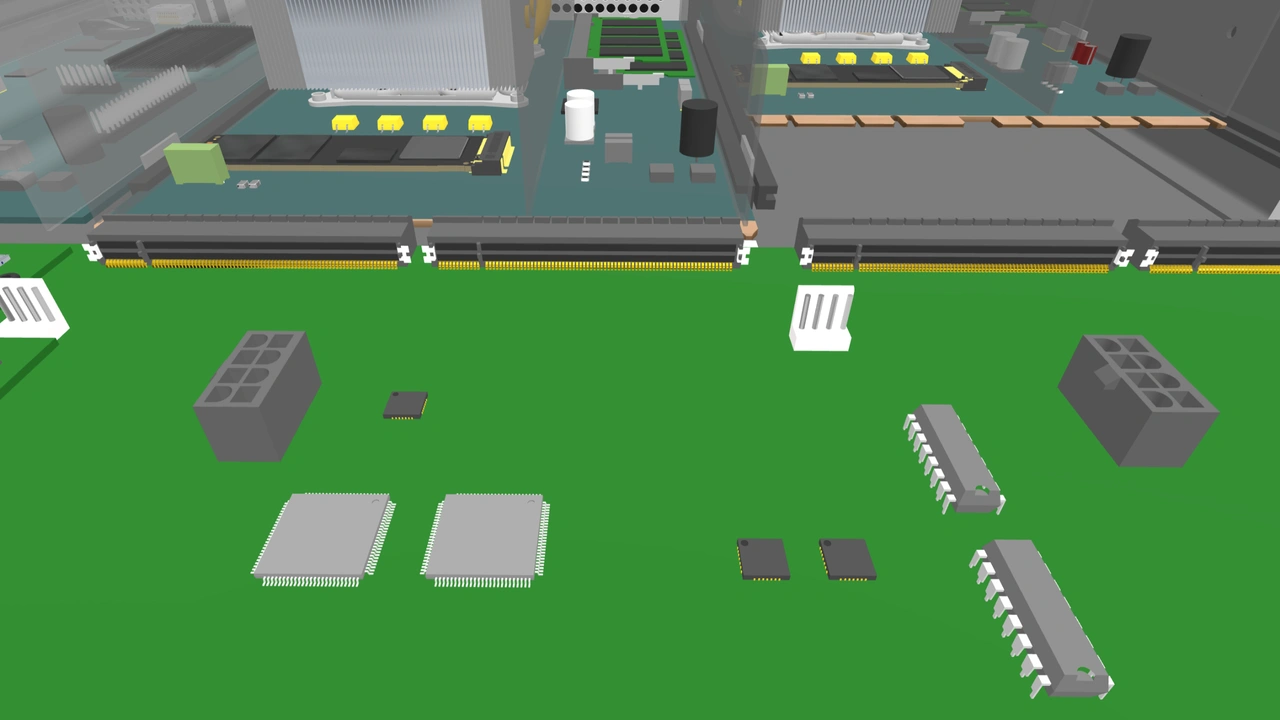
Everything in this step is the OpenSFF-compatible system’s responsibility. Users don’t need to do anything to keep the rest of the system running, including any other nodes installed in the Enclosure.
Power state
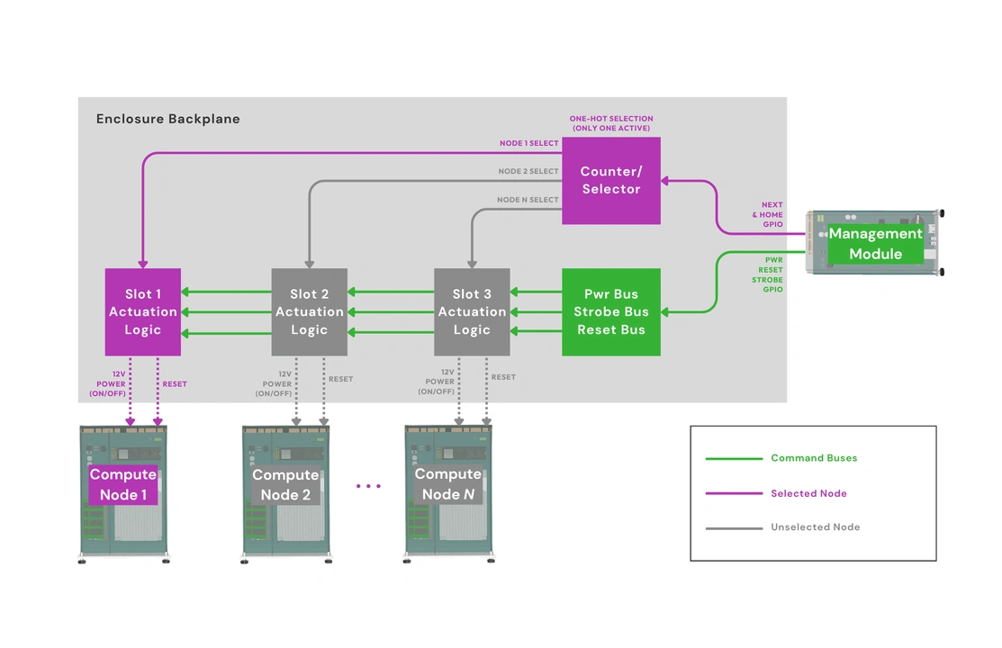
Enterprise Enclosures are required to implement independent node power control and node slot power state monitoring. In other words, removing or power-cycling one node must have no effect on other installed nodes. Vendors designing a Core Enclosure are free to add this feature in their implementation.
Cooling
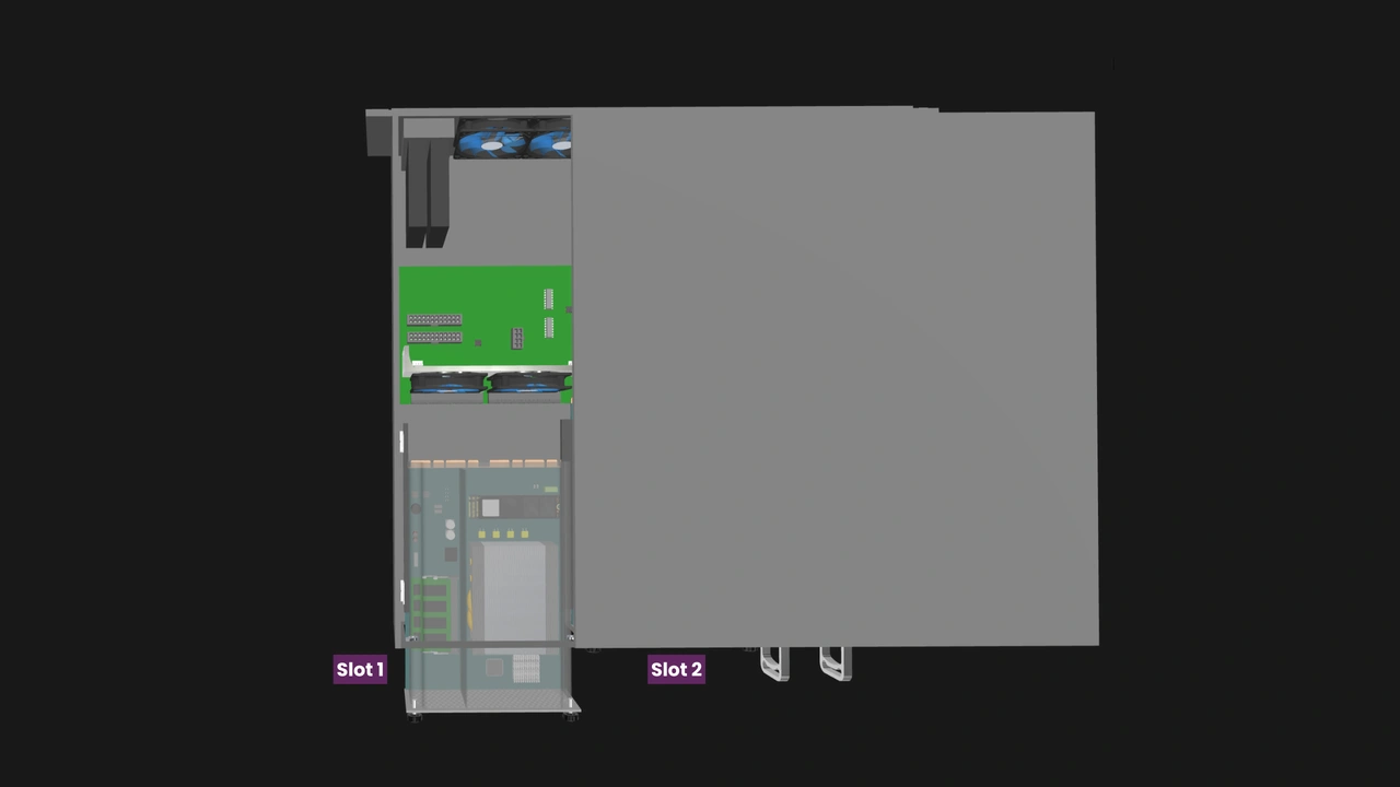
Aside from monitoring and managing a node’s power, the Enclosure also takes care of active cooling. Each Compute Node sends a PWM thermal control signal to the Enclosure to help regulate its assigned cooling fan or fan group. In Enterprise Enclosures, upon learning that the node slot is empty, the installed Management Module flags the slot accordingly instead of initiating the fail-safe.
The Management Module maintains a secondary PWM control path that can override or supplement a node’s signal. When a node becomes unresponsive or stops sending a valid PWM signal, the Management Module will instruct the affected fan or fan group to spin at 100% of its duty cycle.
Node management
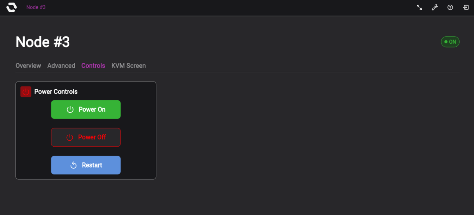
Similar to the node slot status, an installed Full-featured Management Module can also read the Enclosure signals for node presence (whether or not the node is electrically connected) and power state (whether or not the node is using system power) and display that information on the management interface.
Step 4: Close the node slot
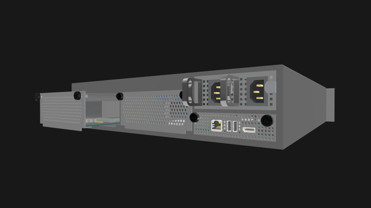
This last step should be familiar to users who have worked with rack-mounted servers. We must fill in the vacated slot with an airflow control feature such as a blanking panel to keep the Enclosure’s cooling path intact. Otherwise, some of the air that the Enclosure takes in will take the path of least resistance, i.e., the empty slot, instead of going through the modules that are still installed. This may result in poor performance or hardware failure due to poor thermals.
Build with OpenSFF
We hope you enjoyed this exploration of some of the minor mechanical and electrical components in an OpenSFF-compatible system. They will work together to make node installation and removal become quick, tool-free, and non-disruptive operations.
We encourage you to read our specifications, and we’d be grateful if you spread the word about OpenSFF. For technical clarifications and other inquiries, reach out to our development team at [email protected].
Other Articles

Meet OpenSFF: an open hardware standard that enables cross-vendor compatibility, modular systems, and sustainable hardware reuse.
August 11, 2025
We go over the rise of virtualization and the open software adopted by home server enthusiasts, as well as the current challenges and the future of the hobby.
September 06, 2025

Learn why OpenSFF adopted the SFF-TA-1002 connector standard and how it enables our vision.
September 18, 2025