Blog
Loosely Speaking: Defining the Module Thumbscrew Requirements
Introduction
Most small form factor PCs and edge devices are sealed boxes. They’re secured with any number of screws, perhaps a strip of tape, and a couple of latches. These retention mechanisms are often the right call in terms of cost, EMI shielding, or industrial protection, but they also make serviceability an afterthought instead of a default option.
Creating servers and devices that are serviceable by design is one of our primary reasons for establishing OpenSFF. We’re a nonprofit organization developing an open-source hardware standard. Our specifications define three components: a processing module called the Compute Node, an active electronic housing for one or more nodes called the Enclosure, and an optional node management component called the Management Module. These three components can be combined to create a wide variety of systems, regardless of their vendors.
Going back to serviceability, we want module swaps to be quick, tool-free procedures. We enforce this principle at multiple points of our specifications, from the connector to the removable Enclosure microSD card. But it’s most evident in our decision to require modules to be secured only by two captive M4 thumbscrews.
It may seem like a trivial aspect, but our specification developer Jon Choi spent a lot of time getting this requirement right. As we’ll explore later in this article, even a few millimeters of tolerance can have a significant impact on our standard’s adoption. Here are some of Jon’s thoughts and findings on defining our module retention mechanism.
Why does OpenSFF require captive M4 thumbscrews?
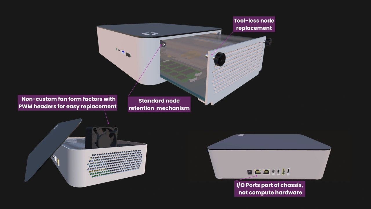
Latches and spring-loaded tabs are commonly used in computers and other electronic devices. However, they often get in the way of serviceability, constrain vendor’s design options, and are more expensive to implement than thumbscrews.
M4 threads are incredibly easy to drill and shape. Vendors can also simply use off-the-shelf threaded inserts that will work with any compliant thumbscrew. On the other hand, a custom latch mechanism is not only more expensive to design, test, and manufacture, it also limits both Compute Nodes and Enclosures to that one design.
Prescribing M4 thumbscrews allows module vendors to choose the exact type of the screw that they want to use based on their budget, product positioning, and intended use case, all without depending on or restricting Enclosure designs.
The captive part of the requirement is much easier to explain. Servers, industrial controllers, routers, and many of the other systems that can have OpenSFF-compatible implementations are often installed in tight spaces where fallen screws can be difficult to recover. A missing screw offsets the convenience and serviceability that our standard offers. Captive M4 thumbscrews also make it easier for even non-technical staff to swap Compute Nodes and Management Modules.
Why two thumbscrews?
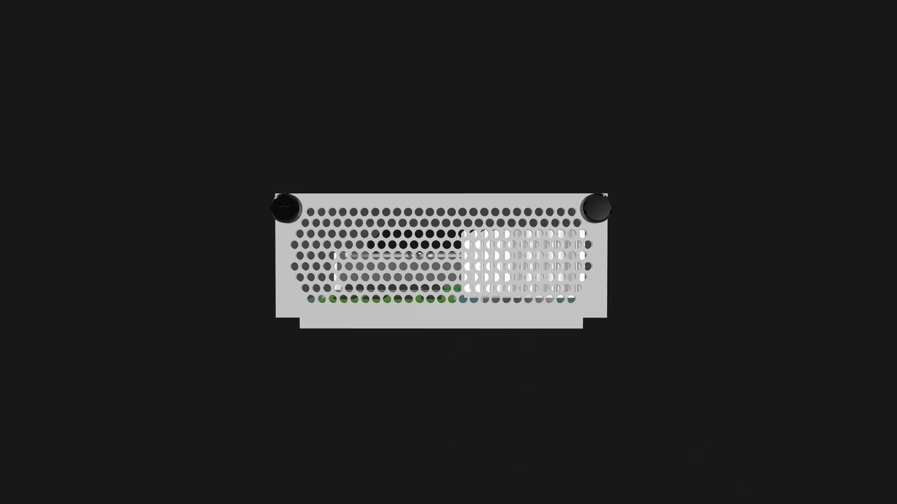
The short answer is that they are more than enough. Even the heaviest graphics cards are secured by only a single captive thumbscrew at the back of a PC case. Heavier GPUs do sag, but that’s not a knock on the thumbscrew. It’s enough to keep the graphics card in place; the card’s bracket is the one that’s not strong enough to prevent the GPU from tilting. Meanwhile, Compute Nodes will be significantly lighter than top-of-the-line GPUs.
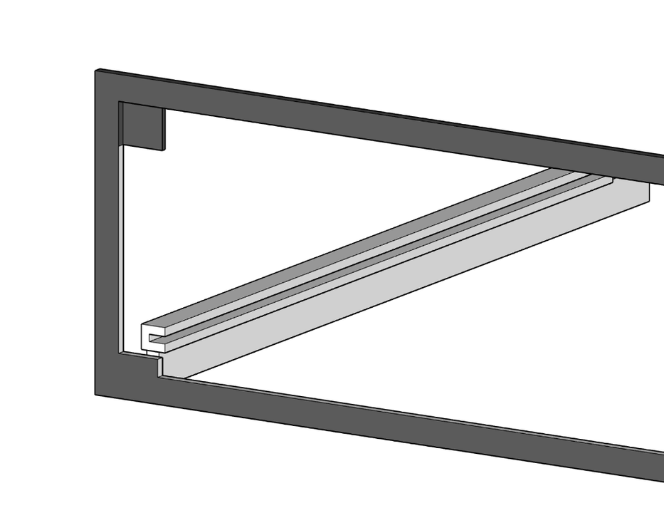
On a similar note, we don’t prescribe a thumbscrew on all four corners of Compute Nodes and Management Modules because the guide rails are located behind the lower corners of our modules. The rails are the ones that will allow the modules to align and smoothly mate with their respective connectors. Adding two more thumbscrews would only give users more parts to deal with for no added benefit.
Why are there screwhole keepout zones on module I/O shields?
Our retention mechanism has one important constraint: the module connectors must fully mate with an Enclosure during insertion without either thumbscrew being tightened. The thumbscrews should be there purely to keep the module in place, not to pull it into its final electrical position. It’s similar to how GPUs don’t depend on their thumbscrew to be fully seated into a PCIe slot or riser.
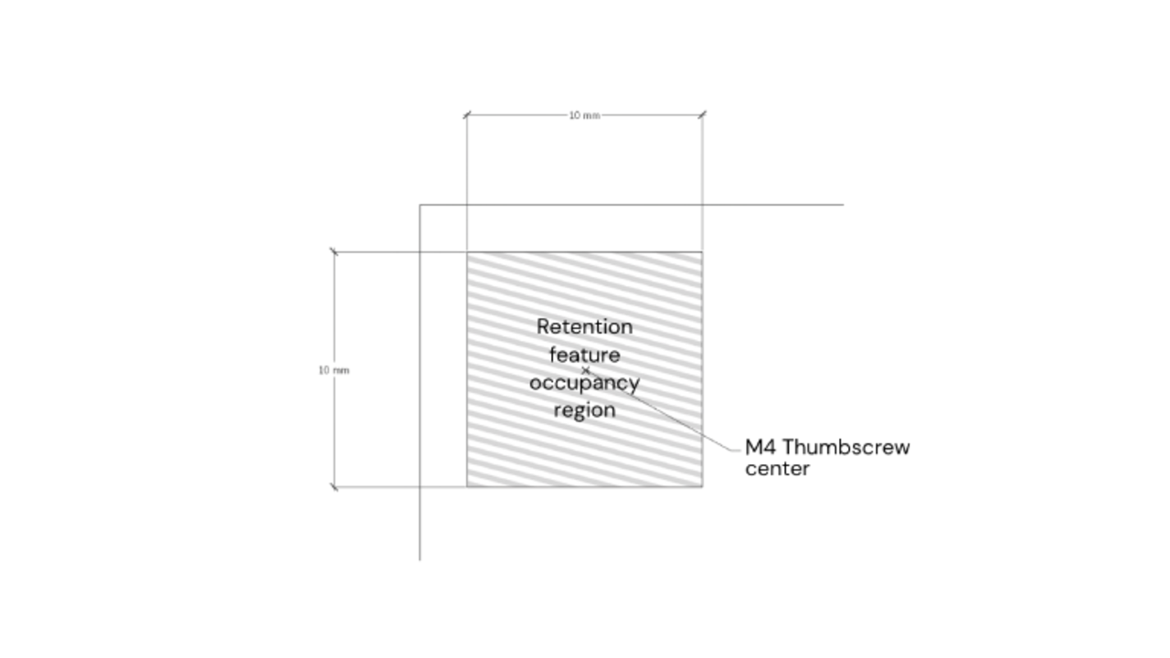
To ensure this, we define our modules’ rear I/O shield to have a 10mm x 10mm zone around each thumbscrew that has to be free of perforations, cutouts, or ports. It allows vendors to come up with a recess geometry for their chosen thumbscrew. Getting to those measurements was quite the journey.
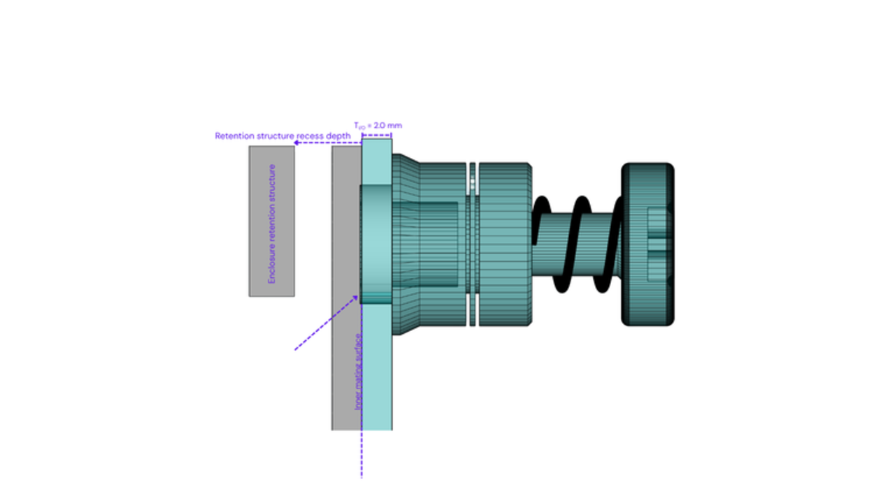
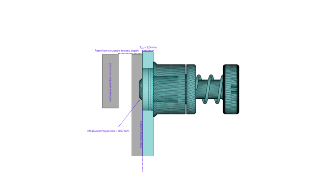
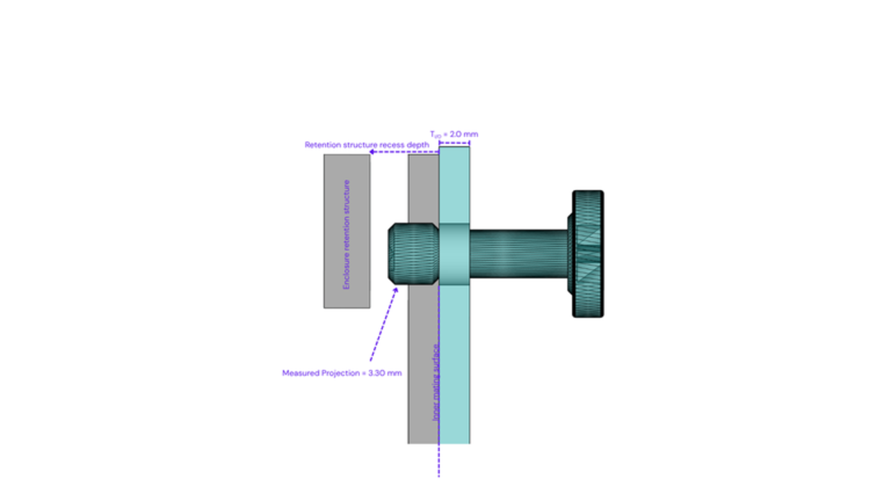
Jon’s initial measurements showed that some inexpensive, commonly used captive thumbscrews could project more than 3 mm behind the I/O shield when fully unscrewed. Accommodating all of those screws directly would have required a recess of roughly 4 mm or more. That would have imposed additional forming depth and manufacturing cost on every compatible Enclosure, including products that used shorter-profile screws.
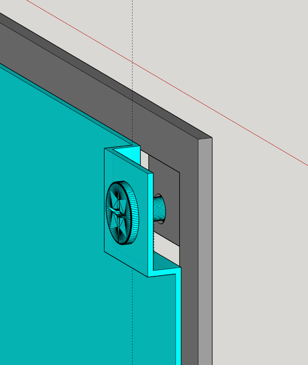
So we moved the flexibility into the modules’ 10 mm × 10 mm keep-out zone instead, and defined a 2mm ± 0.5mm recess depth on the Enclosure’s M4 retention structure. This allows module vendors to choose between shorter screws and local features such as an emboss, captive nub, or folded section.
What captive M4 thumbscrews work with OpenSFF-compatible modules?
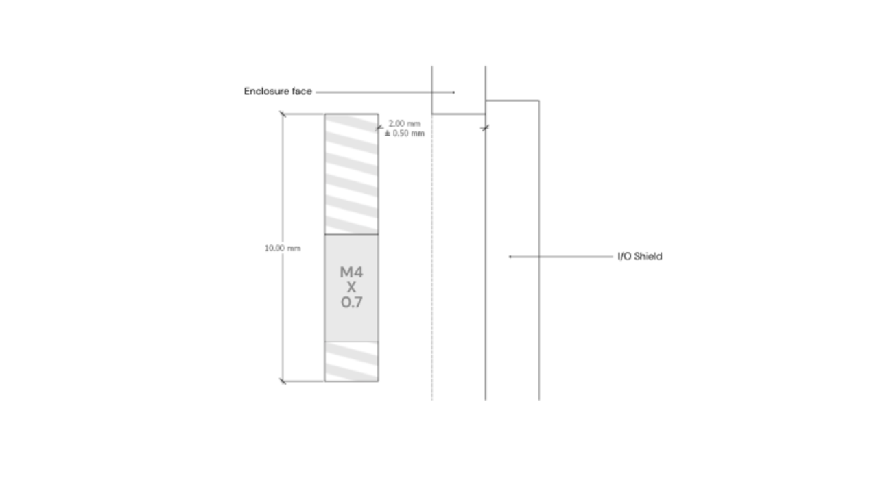
With our measurements finalized, we established our final requirement: when fully tightened, a captive M4 thumbscrew with a smooth shaft or shoulder must retain sufficient threaded engagement within the M4 retention feature. The screw must not be so long that its smooth section passes through the feature. That would make the threaded portion extend beyond the feature, resulting in loss of retention.
Going back to Jon’s thumbscrew measurements, traditional captive thumbscrews are the ones that will ask vendors to be creative with the 10mm x 10mm keepout zones. We’re not sure if there are even 1.5mm deep threaded bits for those screws.
Ultimately, vendors simply have to keep the recess depth in mind, because there will surely be screws that exceed that limit regardless of their type. It’s up to vendors whether to spend more on shorter-profile thumbscrews to keep the I/O shield simple, or to put more effort on designing the I/O shield’s recess so that they can use more affordable thumbscrews.
Build with OpenSFF
A couple of screws and a piece of sheet metal may not seem like they deserve a lot of time and attention. But that’s what most well-designed objects end up doing: solving problems well enough that users don’t have to think about them.
If you enjoyed reading this article, we suggest checking out our software dev updates and other specification-related blog posts. If you want the full details, our specifications are right here on our site as well. For technical clarifications, partnerships, and other inquiries, reach out to our development team at [email protected].
Other Articles

Meet OpenSFF: an open hardware standard that enables cross-vendor compatibility, modular systems, and sustainable hardware reuse.
August 11, 2025
We go over the rise of virtualization and the open software adopted by home server enthusiasts, as well as the current challenges and the future of the hobby.
September 06, 2025

Learn why OpenSFF adopted the SFF-TA-1002 connector standard and how it enables our vision.
September 18, 2025