Blog
A Peek Inside an OpenSFF System
Introduction
The OpenSFF specifications do not focus on physical dimensions or Enclosure sizes. They are mainly about how the three main components - the Compute Node, the Enclosure, and the Management Module - connect and communicate.
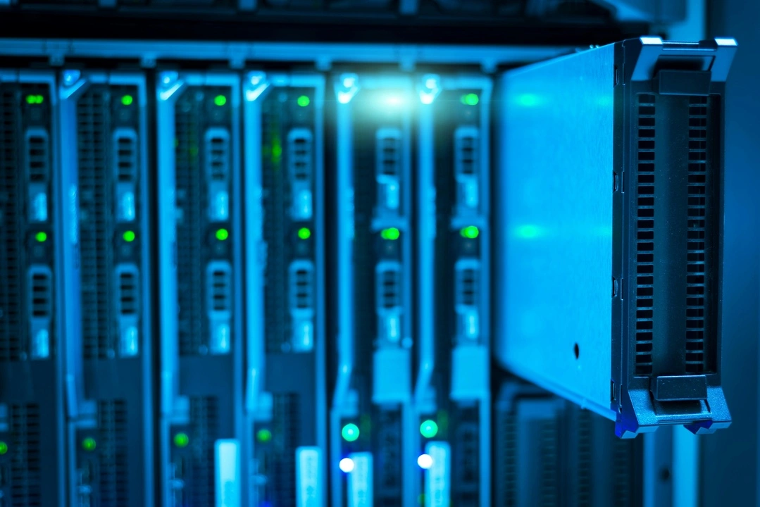
Enclosures are not simply chassis, cases, or housings. They are more similar to blade enclosures than traditional computer cases. Enclosures deliver power to Compute Nodes and expose the Compute Node’s I/O via the SFF-TA-1002 connector. They are also responsible for providing active cooling. Enclosures that have a Management Module slot also provide the same power, connectivity, and thermal solutions to the module.
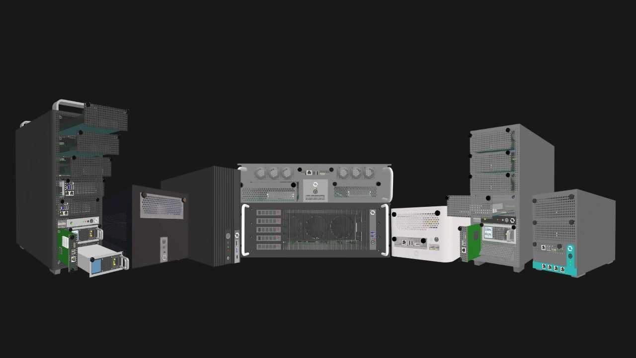
Because of our standard's flexibility, Core and Enterprise Enclosures can differ greatly in terms of their internal layout and parts. Core Enclosures will be much more varied in both form factor and features, from thin clients to multi-node machines. Enterprise Enclosures are purpose-built for managed deployments, with integrated networking, support for redundant power, and remote management.
In this article, we are going to take a look at the key internal parts and features of a sample Enclosure design and summarize how OpenSFF components work together as one system.
The Enclosure backplane
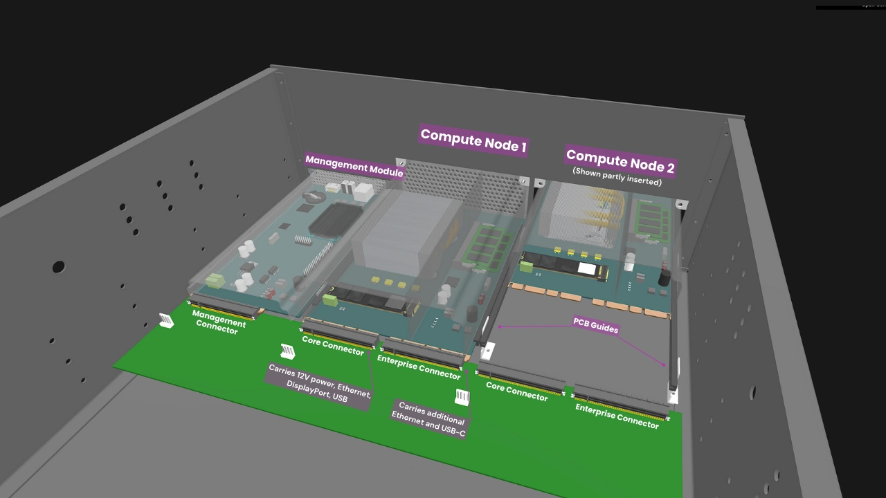
The Enclosure backplane consolidates power, networking, and I/O into standardized connectors. Each Compute Node slot on the backplane hosts a Core Connector. In Enterprise Enclosures, each slot will also have an Enterprise Connector.
The Core Connector carries the essential signals, such as 12V power, Ethernet, USB, and DisplayPort. The Enterprise Connector carries additional Ethernet and USB-C signals.
The connectors eliminate internal cabling and simplify servicing. A Compute Node simply slides into its slot using a blind-mate approach, i.e. there is no need to manually align its socket to the Enclosure connector. Guide rails on the backplane ensure that the Compute Node perfectly mates with the connector every time. The rails also protect the connector from material stress due to vibration and shock. Once the Compute Node is connected, it is secured via two captive M4 thumbscrews located on the top corners of its I/O shield. The same goes for the Management Module in supported Enclosures.
Both Core and Enterprise Enclosures have Core Connectors, enabling interoperability. A Core Compute Node can still be used in an Enterprise Enclosure, though it will have fewer connectivity options than its Enterprise counterpart. Equally important, this straightforward requirement also means that Compute Nodes, Enclosures, and Management Modules are vendor-agnostic.
Power delivery
Each Compute Node slot in an Enclosure delivers at least 120W to the installed Compute Node. Enclosures with a Management Module slot deliver at least 50W to the module. While this rules out high-powered components such as certain Enterprise-grade CPUs and discrete GPUs, the 120W maximum power target is still more than sufficient for a wide variety of CPUs along with multiple storage configurations.
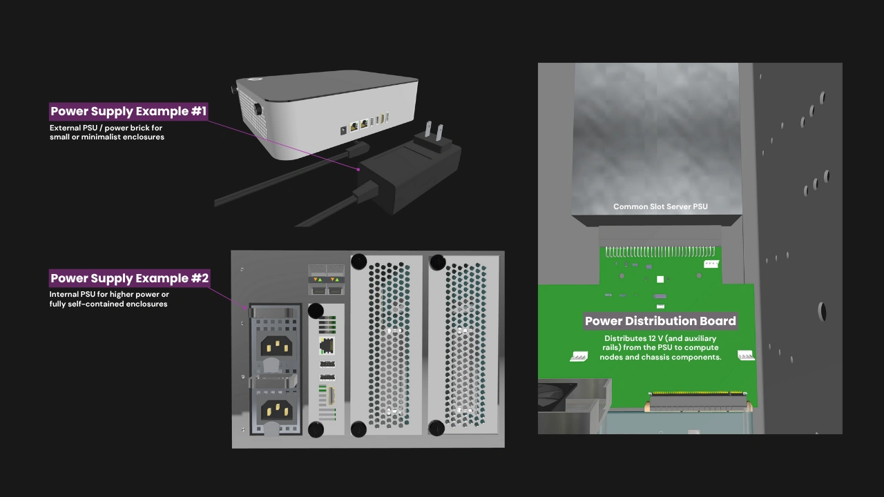
OpenSFF does not dictate the implementation of power delivery in Core Enclosures. Manufacturers can employ everything from compact USB-C charging adapters to redundant PS/2 power supplies (PSU). Enterprise Enclosures on the other hand must have at least two PSU bays with hot-swap support, and must also support redundancy when all bays are populated.
In multi-node systems, the distribution of DC power through the Enclosure backplane is more efficient and thus produces less heat compared to having dedicated AC-DC converters for each Compute Node. This also translates to significant cost savings compared to systems where each node has its own PSU.
Cooling
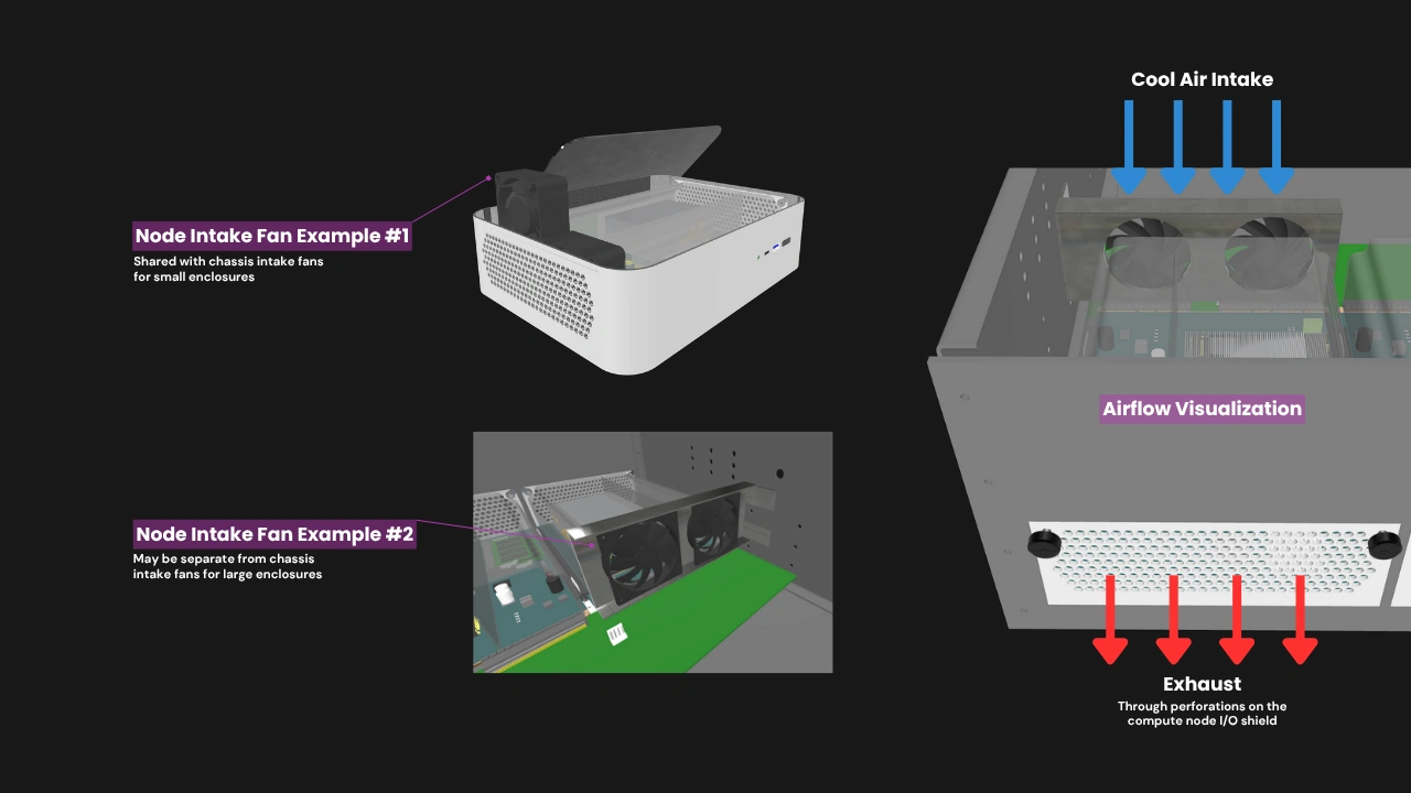
Compute Nodes within an Enclosure rely on directed chassis airflow to meet their minimum thermal requirements. The Compute Node’s major components are passively cooled through its thermal solution (e.g. heatsinks, heat pipes, or vapor chambers), which must function as part of the active cooling setup provided by the Enclosure. Each Compute Node must be designed for front-to-back airflow. Air is brought in by intake fans that are part of the Enclosure, then guided into the plastic shroud that optimizes airflow, and then exhausted through the perforations on the I/O shield.
The Enclosure must not interfere with this flow path. Similarly, the Management Module slot must allow unobstructed convection or forced-air flow sufficient to maintain its thermal envelope under sustained operation.
A multi-node Enclosure must provide a means to preserve airflow continuity if one or more Compute Nodes are absent. This may be achieved using a snap-in airflow blank, bypass duct, or equivalent mechanism that maintains airflow balance and thermal compliance across all remaining Compute Nodes.
Internal networking

In Core Enclosures, each Compute Node’s Ethernet signals are required only to be routed directly to external RJ45 ports on the Enclosure. Meanwhile, Enterprise Enclosures have a Node Network (NN), an internal Ethernet switch fabric that connects all Compute Nodes, eliminating the need for an external switch. Core Enclosures may adopt the NN, but it is required only in Enterprise Enclosures. Both Core and Enterprise Enclosures may have RJ45 or SFP+ ports to connect installed Compute Nodes to external networks.
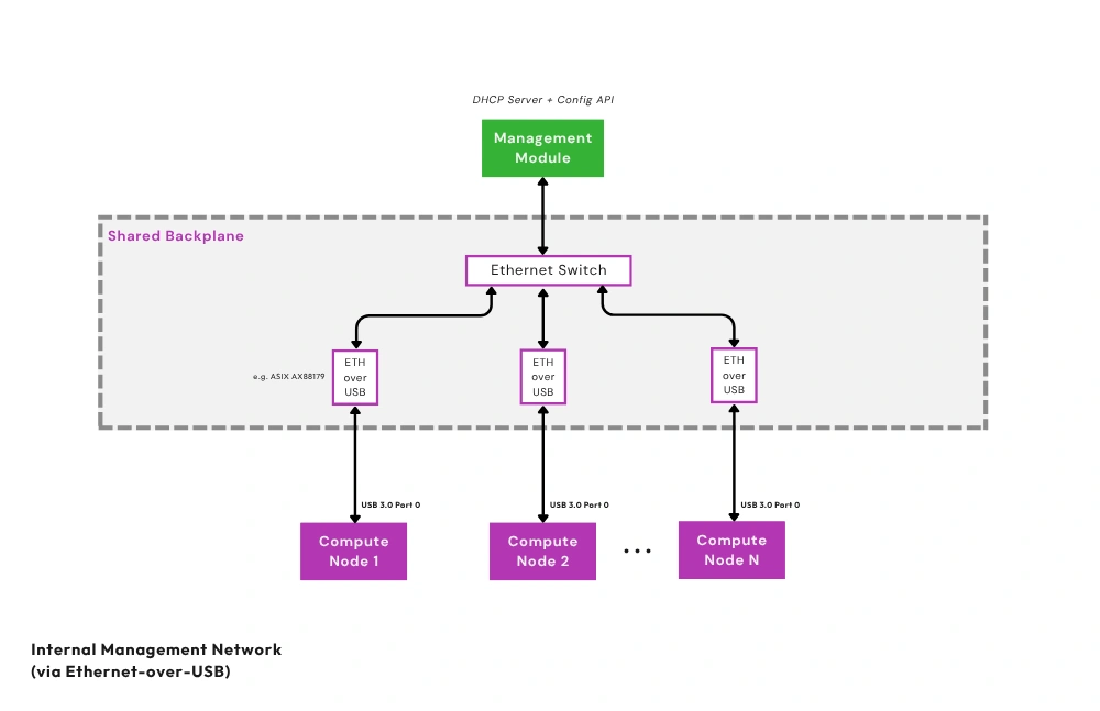
Additionally, Enterprise Enclosures must have a Private Enclosure Network (PEN). This out-of-band network uses Ethernet-over-USB bridges and a dedicated internal Ethernet switch to connect each Compute Node’s management interface to the Management Module. As with the NN, Core Enclosures may also be designed to have a PEN and a Management Module slot. Should users desire to isolate the Compute Nodes from the Management Module, they can disable the PEN via an internal jumper that cuts power to the PEN's Ethernet switch.
KVM and remote management
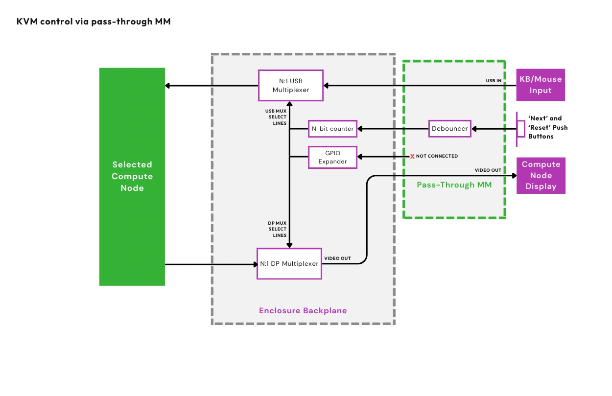
OpenSFF addresses the need for multi-node access and management via signal multiplexing and the Management Module. An installed Compute Node exposes USB 2.0 and DisplayPort signals to the Enclosure. If the Enclosure supports the Management Module, it will have multiplexers to route the USB and DisplayPort signals to the module for KVM access.
OpenSFF defines two reference designs for the Management Module: the Pass-through Management Module simply routes the aforementioned USB and DisplayPort signals to its external ports, allowing it to act as a local KVM device. The Full-featured Management Module is a computer based on the Raspberry Pi Compute Module 5 that enables remote access and management.
Compatible implementations of the Management Module with features or functions that require a computer must be based on Compute Module 5 and run Raspberry Pi OS.
Build with OpenSFF
OpenSFF’s modular architecture is an open, interoperable, and more flexible take on blade servers. Instead of relying on cables and daughterboards, it takes advantage of the SFF-TA-1002 standard and directly involves the Enclosure in connectivity, power delivery, and even remote access and management.
Our specifications allow for systems that scale naturally, from single-node workstations to medium-sized deployments. OpenSFF systems are more space- and power-efficient and vastly cut down on cable clutter compared to existing solutions that connect individual computers as one system.
The connector and the toolless mounting mechanism also make it incredibly easy to install and remove Compute Nodes and Management Modules, making servicing a given instead of a luxury.
Our modular approach also prioritizes component reuse and environmental sustainability. As more Enclosure and Management Module variants become available, the potential for Compute Nodes to serve multiple lifecycles and different use cases drastically increases. As Compute Nodes become more capable and power-efficient, they in turn extend the usability of Enclosures and Management Modules. This self-reinforcing ecosystem can significantly reduce e-waste, as components can easily be passed on from personal to commercial use and vice-versa.
We encourage you to read our specifications, and we would be grateful if you help spread the word about OpenSFF. For technical clarifications, partnerships, and other inquiries, reach out to our development team at [email protected].
Other Articles
Meet OpenSFF: an open hardware standard that enables cross-vendor compatibility, modular systems, and sustainable hardware reuse.
August 11, 2025
We go over the rise of virtualization and the open software adopted by home server enthusiasts, as well as the current challenges and the future of the hobby.
September 06, 2025

Learn why OpenSFF adopted the SFF-TA-1002 connector standard and how it enables our vision.
September 18, 2025