Blog
Open Gateways: The Connectivity Options in OpenSFF
Introduction
The SFF-TA-1002 connector's protocol-agnostic design and exceptional lane density make it a great fit for our standard's modular architecture. The connector not only provides the performance headroom needed for current and future protocols. Combined with our specifications' emphasis on vendor flexibility, it establishes a platform that encourages innovation while maintaining interoperability.
As we mentioned in our dedicated post about vendor options and opportunities, our standard offers plenty of design space for implementing connectivity. The way vendors route, expose, and enhance the standardized I/O signals can lead to numerous practical and creative implementations, from reliable high-performance Enterprise Enclosures to specialized Core Enclosures.
The minimum configuration

Let us go over our standard's baseline connectivity requirements before exploring supplementary connections and specialized implementations.
Minimum required Compute Node signals
Minimum required Enterprise Enclosure interfaces, ports, and signals
Core Enclosures
We showcased in its overview that Core Enclosures have no hard requirements for exposed ports. Vendors can route signals in this Enclosure variant however they desire, including leaving certain signals unconnected.
The maximum configuration
Vendors can create varied port configurations on both Compute Nodes and Enclosures. We calculated practical estimates based on the connector's capabilities as well as our defined dimensions and power budget for the Compute Node.
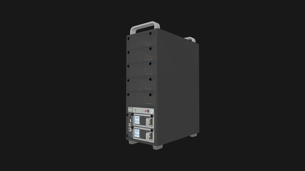
Multi-node Enclosure port capacity
Table 4 shows a rough estimate of the maximum number of Ethernet, USB, and video output ports that vendors can provide in multi-node Enclosures. The Ethernet uplink estimates are based on internal switching implementations with reasonable scaling.
Meanwhile, the USB port estimate assumes that the vendor connects an internal four-port USB hub to the required USB Type-A signals per node slot. That gives us eight USB 2.0 Type-A ports, eight USB 3.0 Type-A ports, and one USB 3.0 Type-C port, for a total of 17 USB ports per node.

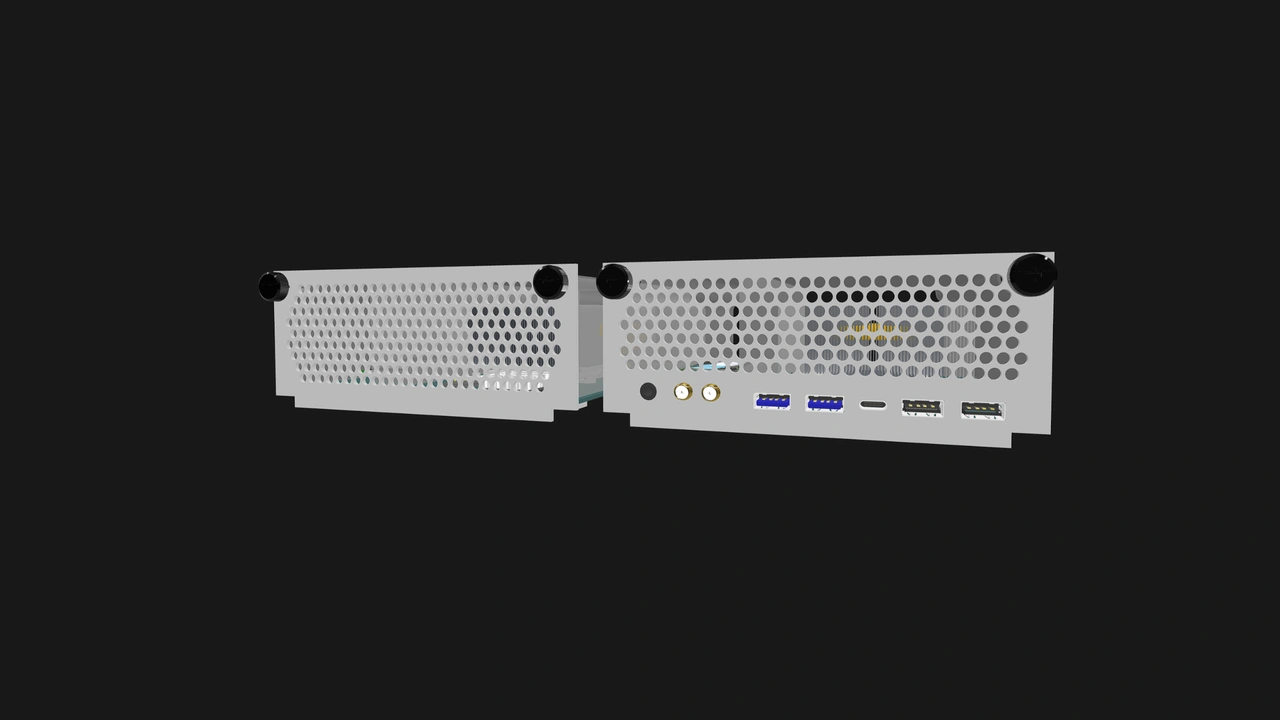
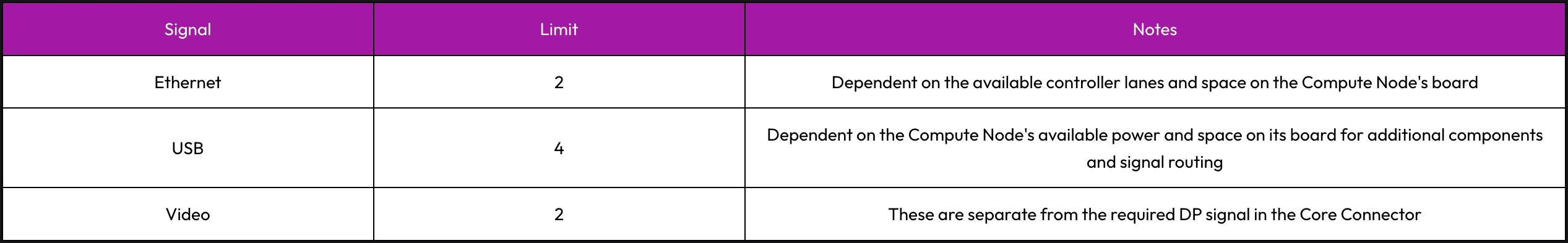
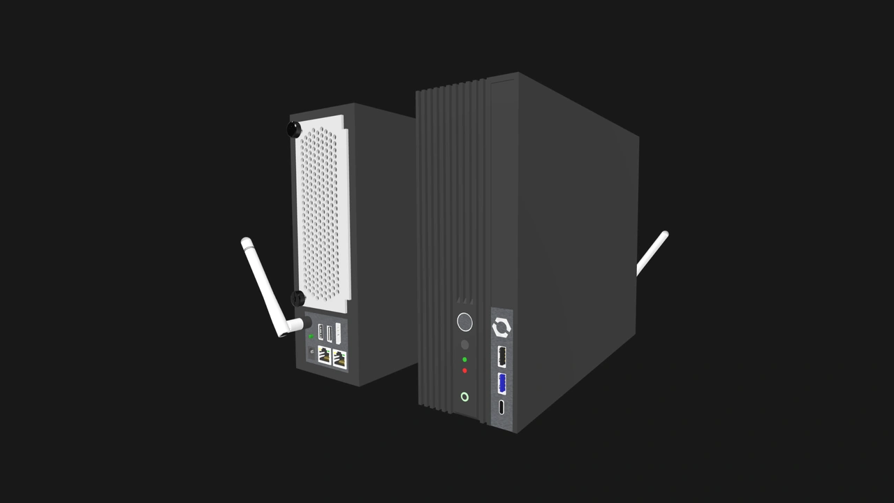
Compute Node I/O shield port capacity
Vendors are not required to provide additional ports on Compute Nodes. That said, there is space for several ports on the I/O shield. This is a prime opportunity for product differentiation and market segmentation. Note that these additional ports are simply that: additional. Compatible implementations that have these extra interfaces must still provide the minimum required signals on the Compute Node's connectors.
While these figures and configurations are by no means definitive, they demonstrate that vendors have more than enough room to differentiate their implementations, even when designing Enterprise Enclosures.
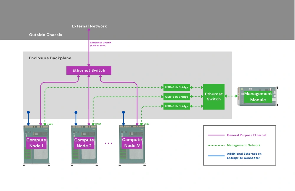
Ethernet connectivity options

The internal switches in Enclosures along with optional Ethernet interfaces provide vendors with a variety of networking configurations with practical use cases.
- VLANs for traffic segmentation: By providing a managed internal switch, vendors can offer users secure and powerful network isolation features. This may be particularly significant in edge devices, as it reduces the system's cost, volume, and complexity.
- Redundant networking: Active-passive failover setups can be achieved even with an unmanaged internal switch. Managed switches on the other hand can be used to configure link aggregation for both redundancy and increased throughput.
- IoT gateway: Two Ethernet interfaces can be used to create isolated networks: one port for IoT devices and sensors, and another port for external connectivity.
- High-speed inter-node fabrics: A high performance Node Network (NN) switch can result in more secure and lower latency node transfers compared to using an external switch. If the internal switch is managed, administrators can also monitor and prioritize certain types of inter-node traffic.
- Unique routing implementations: Multiple Ethernet interfaces can also be used to create an OpenSFF system that can connect to different ISPs or cloud providers at the same time. We also believe it is possible for Enclosures to act as wireless access points. Vendors can integrate Wi-Fi hardware into an Enclosure and use the NN as a backbone.
USB connectivity options

The USB signals in an OpenSFF system can be connected internally to a variety of accessories and devices, such as the previously mentioned USB hub.
USB 2.0 options
- SD or microSD card reader
- Smart card reader
- Hardware security key
- USB-to-RS232 or USB-to-CAN serial adapter
- Environmental sensors
- Home automation controllers such as Zigbee or Z-wave dongles
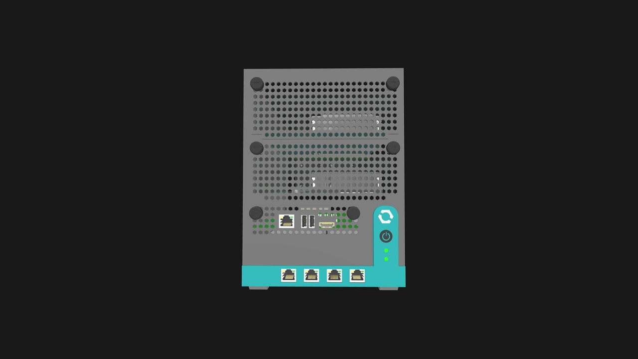
The USB 2.0 ports on the Management Module that are primarily for keyboard and mouse input can also emulate mass storage devices for node management, such as installing firmware updates or operating systems.
USB 3.0 options
- Wi-Fi adapter
- Network adapter
- Audio interface
- Dock or hub
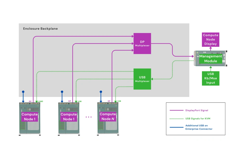
DisplayPort options

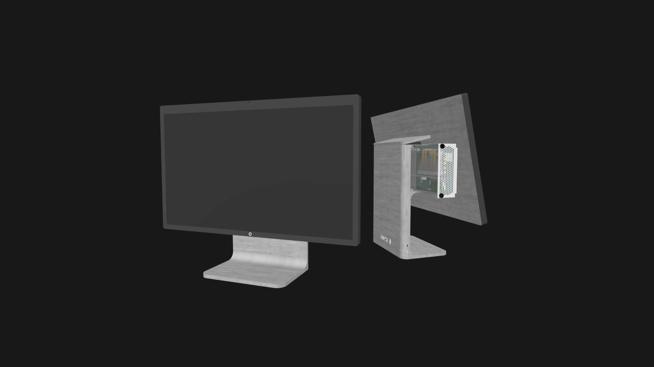
Vendors can create OpenSFF systems that power digital signage in retail stores or information displays in control centers. The video output can also be combined with specialized Enclosures to create touchscreen kiosks. Vendors can also provide integrated display logic to create all-in-one PCs and other appliances with built-in displays.
Other connectivity options
Vendors can supplement the required signals to target specific markets. For example, SFP+ cages on Enclosures can provide high-speed fiber networking. Additional USB-C ports on a Compute Node's I/O shield can make it easier to connect a growing range of peripherals. Audio jacks can be used for media servers, while optical audio outputs can provide high-quality digital audio.
Future versions of the Compute Node specification may also add a 1x PCIe 4.0 lane, which would provide even more expansion opportunities. A basic NAS Enclosure could connect several SATA drives to a Compute Node. Video capture cards can be used for streaming or surveillance. Cellular modems can be useful for remote edge deployments.
Build with OpenSFF
Our standard's connector-based architecture gives vendors plenty of freedom to differentiate, specialize, or innovate. Edge appliances can prioritize support for industrial protocols and have sensors built-in. Enterprise or colocated systems can be equipped with hot-swap indicators or redundant management options. Workstations can have additional USB ports on Compute Nodes for convenience.
The protocol-agnostic design of the SFF-TA-1002 connector also ensures that emerging protocols can be adopted without overhauling the standard. This protects both vendor and user investments and can extend product lifecycles.
The more that vendors and users become familiar with OpenSFF, the more that specialized implementations will be refined. With our requirements for interoperability, these optimized components can easily be combined and repurposed to create a variety of systems.
We encourage you to read our specifications, and we would be grateful if you help spread the word about OpenSFF. For technical clarifications, partnerships, and other inquiries, reach out to our development team at [email protected].
Other Articles

Meet OpenSFF: an open hardware standard that enables cross-vendor compatibility, modular systems, and sustainable hardware reuse.
August 11, 2025
We go over the rise of virtualization and the open software adopted by home server enthusiasts, as well as the current challenges and the future of the hobby.
September 06, 2025

Learn why OpenSFF adopted the SFF-TA-1002 connector standard and how it enables our vision.
September 18, 2025