Blog
Prototyping the Management Module, Part 1: Hardware
Introduction
The Management Module specification defines the device’s minimum requirements and target characteristics. But the document alone won’t give us working hardware or software, so we find ourselves caught between a pair of chicken-and-egg problems.
Managed OpenSFF systems can’t exist without a Management Module, but we can’t fully test the Management Module without Compute Nodes and a managed Enclosure. We also can’t finalize the Management Module’s hardware specifications until we have software to validate it, but we can’t build that software without hardware to test it on.
We can’t afford to wait for a vendor to begin designing and testing their implementation. We want to validate our specification and design philosophy as independently as possible. So we decided to work backwards. We’ve been busy putting together development environments using off-the-shelf components that can adequately simulate production hardware. Here’s how we chose those components to create a pair of test labs.
The Full-featured Management Module
Before diving into the dev environments, let’s recap what the production version of the Full-featured reference design should have. We’re adopting that design to account for smart implementations of the Management Module, as opposed to variants that provide only local KVM and console access.

The Full-featured Management Module is the brain of a managed Enclosure, providing both local and remote access to any installed Compute Node. Compatible implementations of the Full-featured design as well as similar smart Management Modules must be powered by a Raspberry Pi Compute Module 5 (CM5) running Raspberry Pi OS.
We’re working on a default Management Module software that has a Flutter frontend for the web interface and Rust backend services. The latter includes the Management Module server, which encompasses both the Node API and the Platform API, as well as a VNC server for the IP-KVM console.
The Management Module connects to the Private Enclosure Network (PEN), an internal out-of-band network inside managed Enclosures. Users can access one active node console at a time, switching between nodes via the web interface. Vendors can choose to additionally provide a physical interface on smart Management Modules to switch active nodes, but we’ll be focusing on remote node switching for our development environments.
Besides providing local KVM and IP-KVM access, Smart Management Modules also enable remote power control and remote installation of operating systems and firmware. They also work with the Enclosure microSD Card to store and retrieve Enclosure metadata as well as their own configuration file.
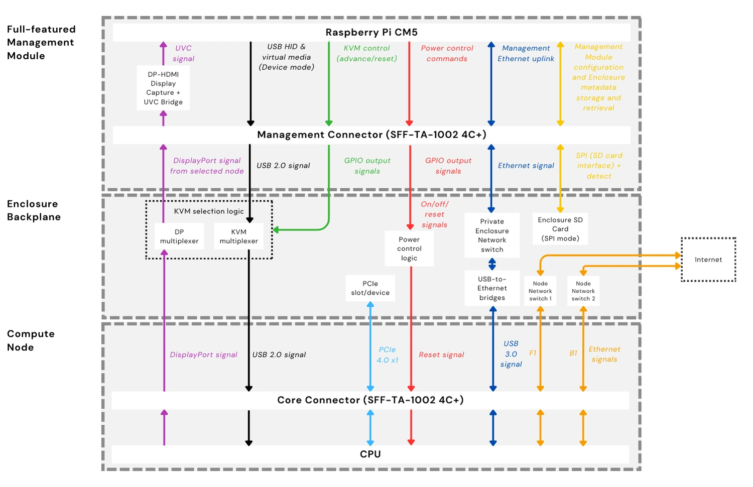
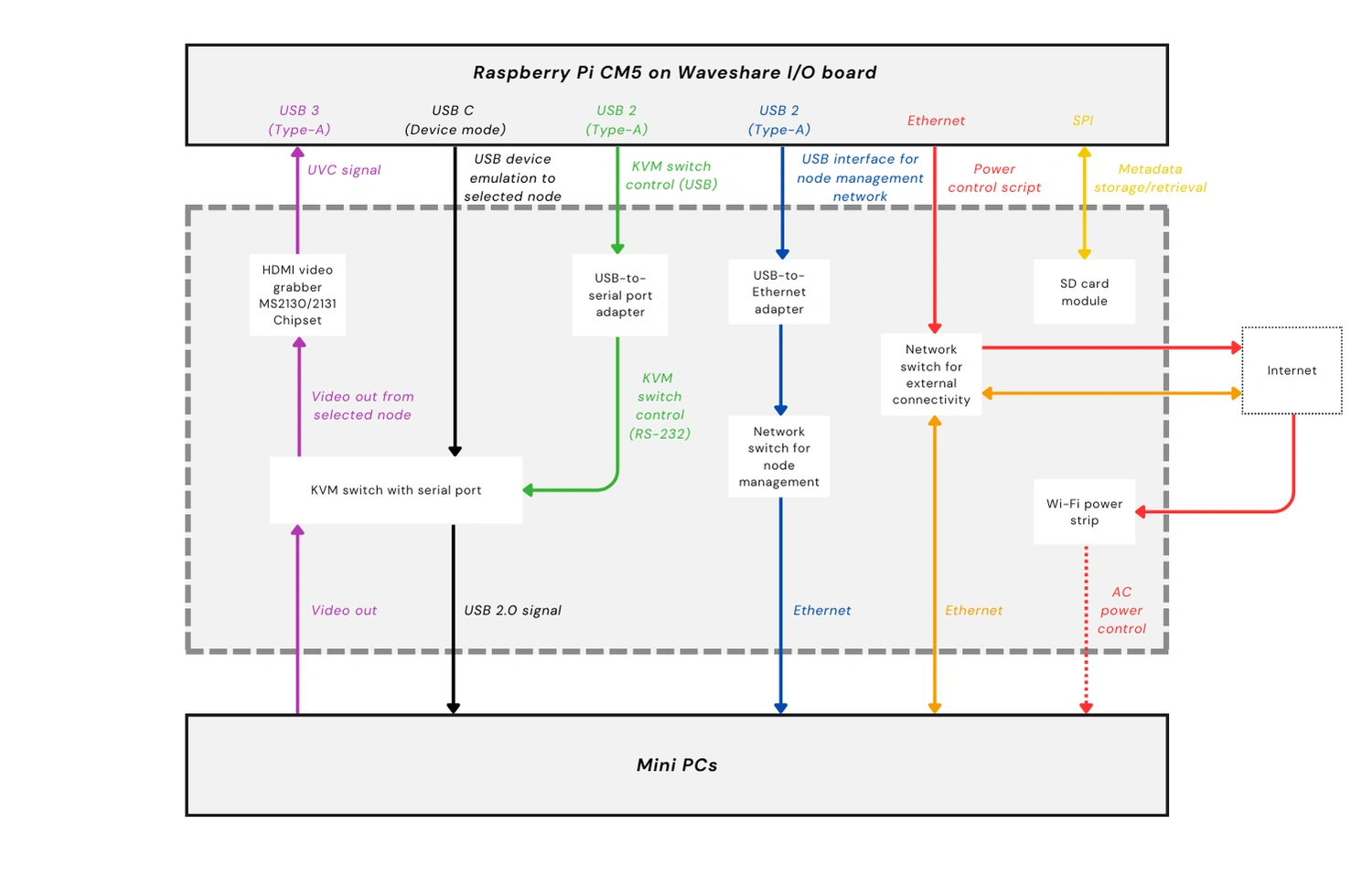
The diagram above shows the target architecture that our dev environment must approximate. It includes the critical components of a Full-featured Management Module, such as a DisplayPort-to-HDMI converter and an HDMI-to-USB Video Class (UVC) capture device to process video signals from the active node. It also shows the relevant Enclosure backplane components, such as the internal network switches for the PEN and the Node Network (NN), which is what Compute Nodes will use to connect to each other and to external networks. As shown in the diagram, compatible managed Enclosures must have at least two network switches for the NN.
Choosing the development hardware
With our production hardware laid out, the team set out to build test labs that would allow us to validate the Management Module software and test how the Management Module, Compute Nodes, and Enclosure backplane components work together. While considering our options, we ran into a few concerns, but we were able to push through and are now finalizing our two dev environments.
Challenge #1: Freeing the USB-C port from power delivery
The team initially considered using the Raspberry Pi 5 to power our dev environments. It’s readily available, well supported, and its built-in I/O would simplify our testing. Jon Choi, OpenSFF’s specification developer, team lead, and hardware designer, quickly reconsidered and settled on the CM5. Not only would the CM5 make our dev environments more closely match our reference design, it would also make us more flexible. We’d be able to take advantage of I/O boards that have a wider range of ports than the Raspberry Pi 5.
This flexibility immediately came in handy because we had a critical issue with the sole USB-C signal on both the Raspberry Pi 5 and the CM5. By default, both computers use USB-C for power delivery. But we need to set that same USB port to Device Mode and connect it to the KVM components on the Enclosure backplane. This would make Compute Nodes detect the Management Module as a keyboard, mouse, and storage device, paving the way for remote installation plus the K and M parts of KVM.

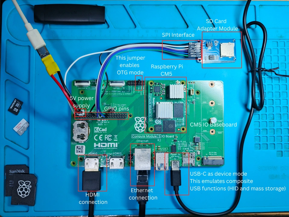
Carlo Jones, OpenSFF’s hardware engineer and software developer, also discovered gaps between the CM5 datasheet (PDF) and Raspberry Pi’s USB OTG white paper. The latter didn’t explicitly state that the CM5’s USB-C signal could be set to Device Mode. To verify this, Carlo paired the CM5 with the Raspberry Pi CM5 I/O board in his dev environment. He then powered the CM5 by connecting a 12V adapter and a buck converter to supply 5V to the board’s GPIO power pins. This allowed him to try and set the board’s USB-C port to Device Mode. As you can see in the screenshot above, the test was successful. But the team wasn’t satisfied with this workaround for power delivery.
While Carlo’s setup was functional, its method of power delivery runs a real risk of accidentally shorting the board while testing. Fortunately, Jon found the Waveshare Electronics CM5-PoE-BASE-A. As its straightforward model name implies, this third-party I/O board can receive both data and power from an Ethernet connection. Not only does this free up the USB-C port, it’s also a better approximation of the production environment, in which the Management Module would be included in the Enclosure’s shared power delivery system instead of having a separate connection to a power source. The team also plans to test whether PoE supplies enough power to drive connected peripherals such as an HDMI grabber, or if we’ll still need an external USB-C power adapter to power those devices.
Challenge #2: Limited USB Type-A ports
While the Raspberry Pi I/O board provided Carlo with a workaround for power delivery, it doesn’t expose the CM5’s USB 2.0 signals and provides only two USB 3.0 Type-A ports. This was a problem because we needed at least three USB Type-A ports: one for an HDMI video grabber, one for a serial port adapter to switch active nodes on the KVM device, and one for a USB-to-Ethernet bridge to simulate a part of the PEN.
We went with the obvious solution for Carlo’s setup: a USB hub connected to one of the official I/O board’s USB 3.0 ports. But once again, Jon’s Waveshare I/O board elegantly solved this issue, thanks to its pair of USB 2.0 ports. Jon still has the option to connect a USB hub if needed, or if he wants to streamline his dev environment even more.
Challenge #3: Remote node power control
In a managed OpenSFF system, users can switch Compute Nodes on or off or reset them through the management web interface. Their command travels through the External Management Network (EMN), which is whatever external network admins will use to connect to the Management Module, down to the module. The Management Module then passes the instructions to the Enclosure’s power control logic on the backplane.
To simulate this feature, the team considered using PDUs that have a serial port, but they’re too expensive to be used as test hardware. So we went with the TP-Link Kasa HS300 instead. It’s a Wi-Fi enabled power strip that can be controlled not only via its mobile apps but also through third-party integration. Most consumers use the latter to connect the HS300 to home automation platforms. In Jon’s case, he enabled it so that he could simulate remote power control with a script based on python-kasa, an open source library for controlling Kasa devices.
Our Management Module development environments
With our challenges solved, choosing the rest of the components became relatively straightforward.
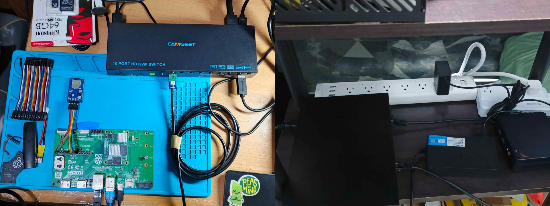
Here’s what our two dev environments look like as of this writing:
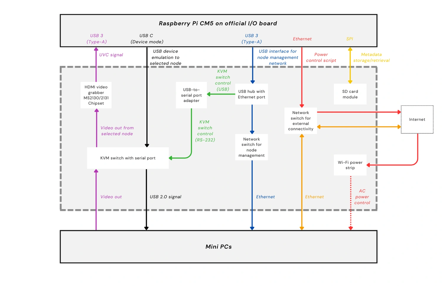
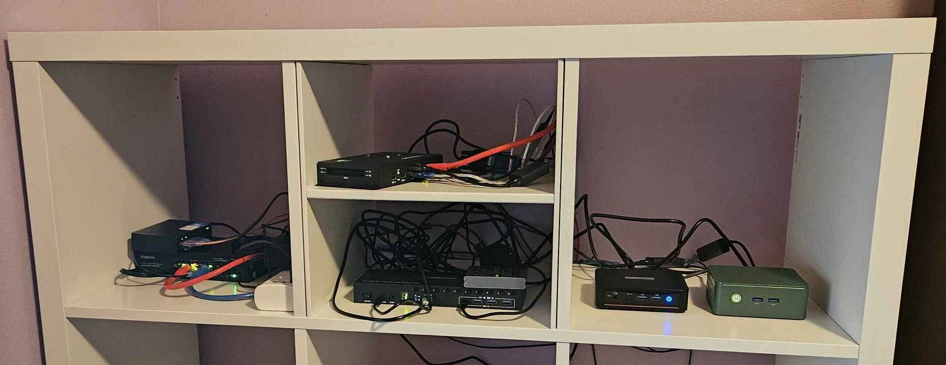

As you saw in the table at the start of this section, the two dev environments are not exactly alike, and both are not yet fully configured as of this writing. But in both setups, the CM5 connects to the same supporting hardware: a KVM switch with a serial port for KVM, node switching, and mass storage emulation, one switch to simulate the PEN, another switch to simulate the NN, a Wi-Fi enabled power strip, and two mini PCs serving as test nodes.
Build with OpenSFF
Once we’ve fully assembled our dev environments, we’re confident that we can sufficiently validate the Full-featured Management Module reference design. We just need to configure remote access for our software team.
Speaking of which, our next development update will be about our progress with the Management Module software. Lead developer Aldrin Bobita and his team will share their approach, challenges, and insights regarding creating the API, the VNC server, and the frontend.
Thank you for joining us on our journey from documentation to deployment. If you enjoyed reading this, we encourage you to keep an eye on this blog. When we’re ready, we’ll be back with another development update. We’ll share our test results and any lessons that we can apply as we continue to refine our standard.
We’d also be grateful if you could help spread the word about OpenSFF and our specifications. For technical clarifications and other inquiries, reach out to our development team at [email protected].
Other Articles

Meet OpenSFF: an open hardware standard that enables cross-vendor compatibility, modular systems, and sustainable hardware reuse.
August 11, 2025
We go over the rise of virtualization and the open software adopted by home server enthusiasts, as well as the current challenges and the future of the hobby.
September 06, 2025

Learn why OpenSFF adopted the SFF-TA-1002 connector standard and how it enables our vision.
September 18, 2025