OpenSFF Compute Node Specification
Download as PDF4. Electrical Specifications
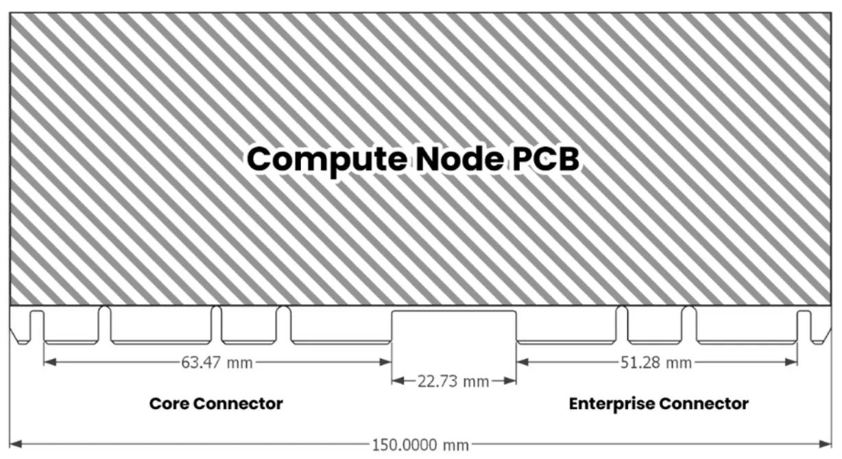
4.1 Connector Layout
The connector layout for the compute node MUST be as follows:
- Core Connector
- Position: 0 mm from the left side of the system board (with plug connectors facing towards)
- Guide notch location: On each side of the connector plug for Core variants. For Enterprise variants, only on the outer edge (away from the Enterprise Connector).
- Enterprise Connector (Enterprise node only)
- Position: 0 mm from the right side of the system board
- Guide notch location: The Enterprise connector’s notch must start flush with the rightmost side of the board.
- Spacing: 22.73 mm between the Core Connector and Enterprise Connector (if present)
- Inner Latches: If both connectors are used, no guide notches should be present on their inner sides (the sides facing each other).
4.2 Power Requirements
- The compute node MUST be powered by 12 VDC through the Core connector.
- The compute node MUST support a maximum power consumption of 120 Watts.
4.3 Ethernet
The compute node MUST support Ethernet connectivity as follows:
- Number of ports: Two ports through the Core connector and an additional two ports through the Enterprise connector
- Speed: 2.5 Gbps
- Connector type: RJ-45
4.4 USB
The compute node MUST support USB connectivity as follows:
- Number of USB 2.0 ports: Two
- Number of USB-C ports: One port through the Core connector and an additional port through the Enterprise connector, supporting at least USB 3.0 speeds
- Number of USB 3.0 ports: One allocation for a Type A connector for external use or as an interface for node and management communication over Ethernet (mentioned in Sections 2.1 and 2.2).
4.5 DisplayPort
- The compute node MUST support DisplayPort connectivity with a minimum version of 1.4.
4.6 Front Panel Connectors
The compute node MUST provide connectors for front panel functionality, including:
- Power button
- Reset button
- Front panel audio (stereo line out and mic)