OpenSFF Enclosure Specification
Download as PDF4. Power Delivery and Thermal Requirements
OpenSFF enclosures must provide consistent, reliable power and cooling to all installed compute nodes. This section defines the baseline requirements and recommendations for electrical power infrastructure and chassis-level airflow performance.
4.1 Power Delivery
4.1.1 Enterprise Enclosures
Enterprise Enclosures MUST implement a centralized power distribution system that provides coordinated and redundant power to all compute nodes and the management module.
This system MUST:
- Deliver up to 120W per compute node slot
- Deliver up to 50W to the management module slot
- Support the combined current draw of all installed components under full load
- Provide DC power lanes to all slots, including the management module, via the 4C+ connector (See Section 5.1.1 of the OpenSFF Compute Node Specification)
To ensure serviceability and continuous uptime, the enclosure MUST support redundant and hot-swappable power supply units (PSUs). Specifically:
- It MUST include two or more PSU bays with hot-swap mechanicals and connectors
- It MUST support redundant operation (e.g., N+1 or N+N configurations) when all bays are populated
- Systems MAY ship with only one PSU installed, provided the chassis can be expanded to support a redundant configuration when needed
4.1.2 Core Enclosures
Core Enclosures are not required to implement shared or centralized power delivery systems.
The method of power delivery is vendor-defined, provided that:
- Each compute node receives sufficient power to meet its operational envelope
- Power delivery does not interfere with node removal, servicing, or replacement
- All safety and electrical compliance requirements are met
Core Enclosures MAY optionally include shared power infrastructure or a powered Management Module slot. However, their classification remains Core unless all Enterprise requirements (as defined in Section 2.1.1) are satisfied.
4.2 Thermal Management
Compute nodes within an enclosure rely on directed chassis airflow to meet their minimum thermal requirements. The enclosure is responsible for managing airflow in a way that ensures consistent cooling across all occupied slots.
To meet these requirements, enclosures MUST actively manage airflow and thermal continuity across all occupied slots.
4.2.1 Enclosure Responsibilities
The enclosure is responsible for:
- Ensuring that airflow is delivered to the compute node’s shroud inlet, not merely to the vicinity
- Maintaining clear flow paths, fan provisioning, and airflow guides as needed
- Avoiding blockage of the rear I/O exhaust area, where the node is designed to expel heated air
- Providing a means for fan speed control that can be driven by compute node logic or the management module (See Section 4.2.4)
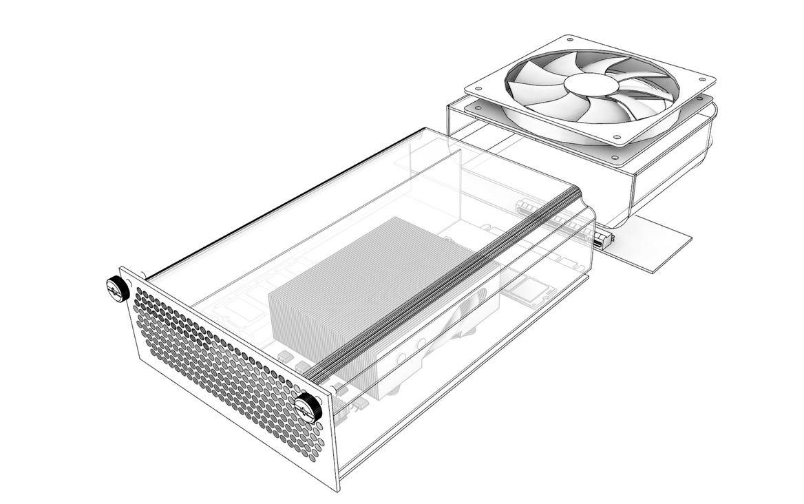
The compute node’s cooling shroud is designed to channel airflow through its heatsinks and components, exhausting air through the rear I/O shield perforations. The enclosure MUST NOT interfere with this flow path. Similarly, the management module slot MUST allow unobstructed convection or forced-air flow sufficient to maintain its thermal envelope under sustained operation.
4.2.2 Airflow Requirements
At each occupied compute node slot, the enclosure MUST deliver:
- Airflow Volume: 68 cubic meters per hour (68 m³/h)
- Static Pressure at 68 m³/h: 11.95 mmH₂O (millimeters of water column)
These values represent the minimum effective airflow required to support a 120W thermal envelope per compute node under full load. Enclosure designs must guarantee this requirement
across all occupied slots.
Note: When a compute node is absent, the enclosure MUST preserve airflow continuity through the affected slot. This MAY be achieved using a snap-in airflow blank, bypass duct, or equivalent mechanism that maintains airflow balance and thermal compliance across all remaining nodes.
4.2.3 Airflow Direction
Provided the conditions below are met, an OpenSFF compatible enclosure may use any airflow implementation:
- The inlet of each compute node’s shroud still receives the required airflow volume and pressure
- The cooling path is isolated from recirculation zones
- The enclosure does not interfere with the node’s own airflow routing and exhaust
4.2.4 PWM Control Behavior
Fan speed control in OpenSFF systems is initiated by compute nodes, even though the fans themselves are implemented as part of the enclosure. Each node is responsible for regulating the airflow through its cooling shroud using PWM (Pulse Width Modulation) signals routed through the connector interface. To support this behavior, the enclosure MUST route PWM lines between each compute node slot and the fan or fans responsible for delivering airflow to that node’s inlet. Each fan or fan group SHALL be driven by one node’s PWM output under normal operating conditions.
The enclosure is responsible for:
- Physically implementing the fan array and ensuring correct routing of PWM signals from each node to its assigned fans
- Guaranteeing electrical isolation between PWM lines to avoid contention between nodes
- Ensuring that each fan or fan zone is controlled by a single node at any given time
In Enterprise Enclosures, or in Core Enclosures equipped with a Management Module (MM), the PWM lines SHALL include a hardware-level failsafe to maintain airflow in the event of node failure or unexpected behavior. The MM MUST provide a secondary control path that can override or supplement node-driven PWM outputs.
A simple and recommended implementation is to logically OR the MM PWM signal with each node’s PWM output. Under normal operation, the MM PWM output remains inactive (logic low), allowing the node to retain full control. If a node becomes unresponsive or fails to output a valid signal, the MM asserts its PWM line high (logic high), forcing all fans to spin at 100 % duty cycle.
Alternative mechanisms that achieve the same functional behavior MAY be implemented, provided they meet the same reliability and response requirements.
When maintenance requires a node to be removed, the MM SHOULD mark that slot as “not installed” to prevent unnecessary fan operation.